

联系我们
If you need assistance, please reach out to us.
Phone: (800) 226 – 1013
Email: mctrans@ce.ufl.edu
为了更好地帮助您,请准备好您的TSIS版本号或激活号码。您可以通过选择“Help”,然后点击“About TSIS”找到。如果方便,请分享输入或项目文件,这将有助于我们解决您遇到的问题。
提示和常见问题
以下是我们最常被问及的问题。
Network Editing (TSIS) FAQ
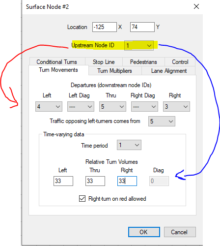
For each node, users must specify turning movements and volumes for every linked upstream node (highlighted). Each traffic movement from an upstream node must be linked to at least one destination node, ensuring that the destination is not the same as the upstream node. Additionally, users must detail the expected traffic volume for these turns, which can be presented as a total demand, in proportional ratios, or as a percentage out of 100. When specifying to/from entry/exit nodes, there must only be a through movement of volume 100. It’s important to note that TSIS-CORSIM will automatically generate turning movements and volumes when attaching links between nodes, but users should verify their results, as only some approaches may be automatically modeled.
Two-way left-turn lanes are easily modeled by coding a node with left-turn pockets at any location along the link where left-turns can be made.
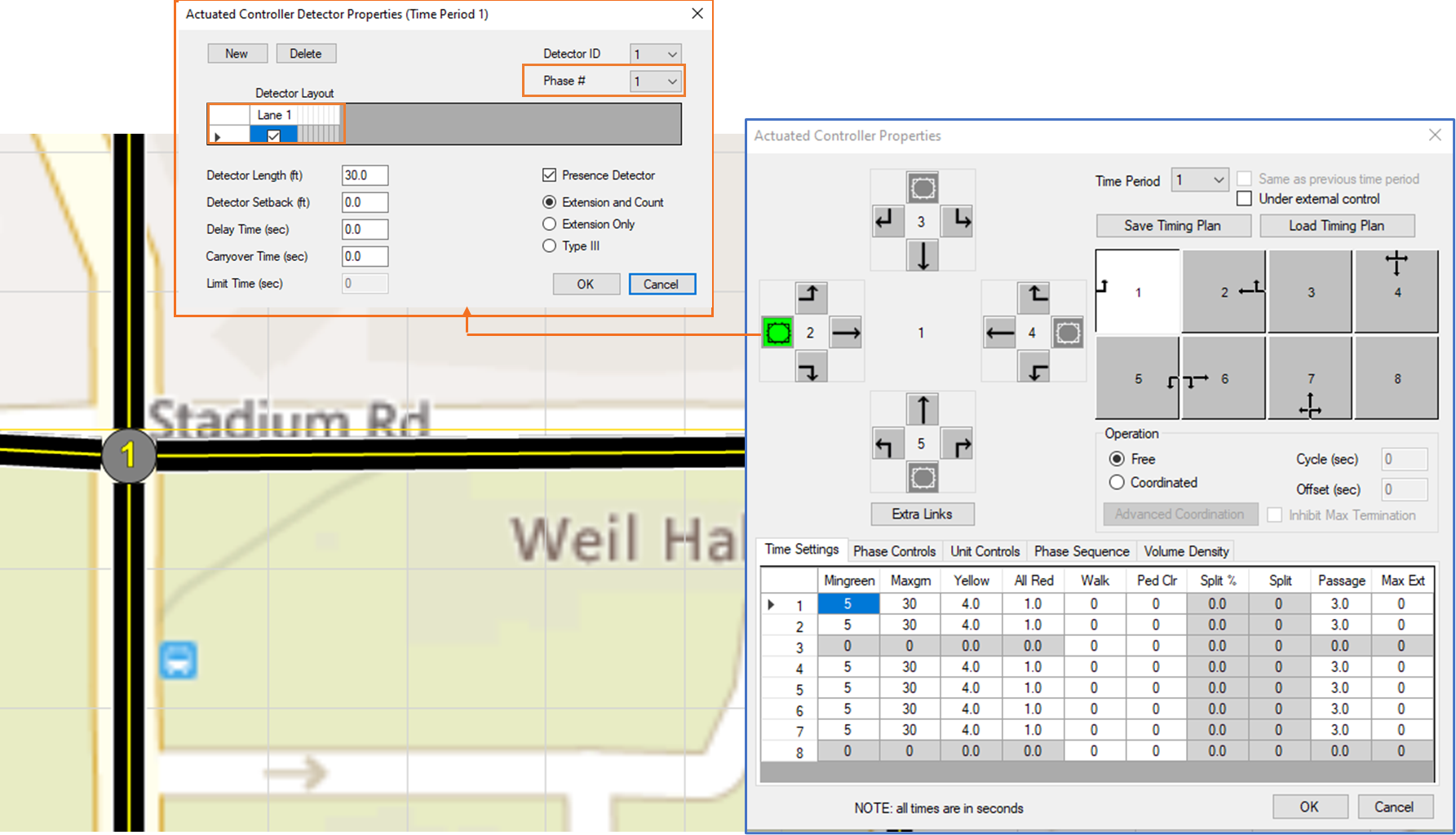
Make sure fully actuated signal controllers have detectors set at all appropriate link approaches. Independent detectors should be set for each lane used by the corresponding signal phases.
By default, freeway capacity is approximately 2200 vehicles per lane per hour (vplph) in FRESIM. Highway Capacity Manual chapter 8 indicates that freeway capacities between 1700 vplph and 2600 vplph have been measured across the U.S. By calibrating various settings, FRESIM can be made to simulate a wide range of freeway capacities. Many of these freeway calibration settings can be coded in TSIS, under Network > FRESIM Setup. A sample input file called “Max Capacity.trf” illustrates capacities above 3000 vplph, even though such high capacities are unrealistic. To access this sample file, click on the “Sample Data Files” link at the top of this page. Although there is no explicit input parameter for freeway capacity, some of the input parameters potentially affecting freeway capacity include:
- threshold speed and distance for anticipatory lane changing
- global and link-specific car following sensitivity factor
- minimum separation for vehicle generation
- off-ramp warning sign distance
- free flow speed distribution
- vehicle lengths
Note that when conditions are oversaturated in the real world, multi-period simulation may be needed, to allow all input volumes to be served. The beginning of the first time period should be undersaturated, and the end of the final time period should be undersaturated.
Simulation Viewer (TRAFVU) FAQ
Yes. Bitmaps are stored on disk differently depending on the type of bitmap. 24-bit color bitmaps use 3 bytes per pixel, 256 color bitmaps use 1 byte per pixel, 16 color bitmaps use 2 pixels per byte, and black and white bitmaps use 8 pixels per byte. So the size of the file can change dramatically based on the type of bitmap. Depending on the image that is trying to be loaded and the purpose of the image, reducing a 24-bit color image to a 256 color image could buy a lot better resolution. Orienting the image so the longer direction is vertical could allow a bigger bitmap than orienting it horizontally. You can use Microsoft Paint, or other graphics programs, to reduce the amount of colors in the bitmap (by using File > Save As). TRAFED can handle both JPG and BMP, but the current version of TRAFVU can only handle BMP files. You can use graphics programs to save JPG files as BMP files, if needed.
This is usually caused by a bitmap filepath that exists in the TRF file, but does not exist on the target computer. The problem can usually be solved by deleting the bitmap background path data at the bottom of the TRF file, or by deleting the filepath (in which case the bitmap background file must reside in same folder as the TRF file), or by fixing the bitmap background filepath. In other more rare cases, where a TRAFVU crash is unrelated to the bitmap background filepath, it may be best to send your TRF file to McTrans for further testing.
This usually indicates a mismatch between the link length input to CORSIM (which is the distance from the upstream stopbar to the downstream stopbar) and the link length calculated by TRAFVU (which uses node coordinates and the location of other links to determine where the stopbars are located). That mismatch forces TRAFVU to stretch or compress the link, in order to be consistent with the node coordinates. Since it draws vehicles the same size (for each vehicle type) it sometimes appears that the vehicles are farther apart, and it sometimes appears that they are overlapping each other.
The solution is to enter consistent link lengths and node coordinates. TRAFVU locates the node at the point where the left curbs intersect. The location of the stopbars is then determined by the way the links connect and the number of lanes on the links. Read section 3.3.2 in the TRAFVU User’s Guide for more details.
The node to node distance is not necessarily equal to the link length. The link length is the stopbar to stopbar distance. The intersection width needs to be added to the node to node distance. Select the link in TRAFVU and right click the mouse. Select Geometric Data, and compare “TRAFVU calculated length” to “Length”. Those numbers should be the same, or nearly the same. If they are different, take the TRAFVU calculated length and use it as the link length.
Simulation (CORSIM) FAQ
Each object category has a checkbox next to the name that can toggle all objects of that category on or off.
The green phase of a FRESIM ramp meter often lasts 1 second; but the first vehicle in queue, or the first two if “two per green” is enabled, is allowed to proceed and then ignore the signal. In some cases the problem is a lane drop warning sign, which is located directly on top of the node where the ramp meter is located. It will work if the warning sign is moved 1 foot downstream to allow vehicles to respond to the ramp meter and then respond to the lane drop, instead of trying to respond to both of them at the same point. In other cases, Startup Delay should be changed on the ramp metering link. For example, a Startup Delay of 0.1 seconds will sometimes produce much higher capacities than a Startup Delay of 1.0 seconds.
Some techniques for avoiding premature actuated phase termination in NETSIM are as follows:
- The gap reduction code should be ’0′ instead of ’2′.
- The maximum initial interval should be equal to the minimum green.
- Min recall should be activated to avoid phase skipping, if phase skipping is not desired.
- The minimum gap should be 2.0 seconds or higher.
Simulation Warnings Messages FAQ
CORSIM networks contain no vehicles at the beginning of a run. As the first seconds are simulated, vehicles are emitted onto the network from entry and source nodes. The time required to fill the network with traffic is referred to as the initialization period. Since the initialization period does not accurately represent the conditions to be modeled, no statistics are gathered during this period. A check is made at the end of every time interval for equilibrium, i.e. the end of initialization. Equilibrium is assumed when the number of vehicles in the network is within 8% of the number of vehicles in the network during the previous time interval, and within 12% of the number of vehicles in the network during the second previous time interval. In the CORSIM output file, this information is reported in the section called “Initialization Statistics”.
This is usually caused by the lane drop warning sign distance. The warning sign for a lane drop should never be at a location with only one lane. The warning sign location is really the point at which vehicles respond to the object associated with the warning sign. If there is only one lane at the point, or only one lane usable by certain vehicles, the warning sign will be ignored.
Fatal error messages 6197 and 6198 are often caused by a missing record type 25. Off-ramps are defined by record type 25. For the mainline link, record type 25 must be coded to indicate which node receives off-ramp traffic. Without record type 25, CORSIM cannot locate the off-ramp destination node. When all of the necessary record type 25′s are entered, this allows the origin-destination inputs on record type 74 to function properly.
资源
软件演示
See a live demonstration of TSIS-CORSIM.
Installation Help
Find information on how to download, install, or remove the software.
Known Issues
We are continuously updating our software. See the document of known issues.
