
Dr. Ehsan Amini
The “2×1 Roundabout” (Figure 1) configuration offers a practical solution to enhance safety and efficiency at multi-lane roundabouts. This design is particularly effective in reducing the frequency of minor collisions often seen at roundabout exits. By minimizing conflict points and optimizing lane usage, the 2×1 configuration creates a smoother and safer traffic flow. This guide is intended for traffic engineers and planners seeking to implement more reliable roundabout designs in areas with significant traffic volumes. The following instructions will walk you through the process of modeling this configuration in TSIS-CORSIM, complete with illustrative examples and screenshots.
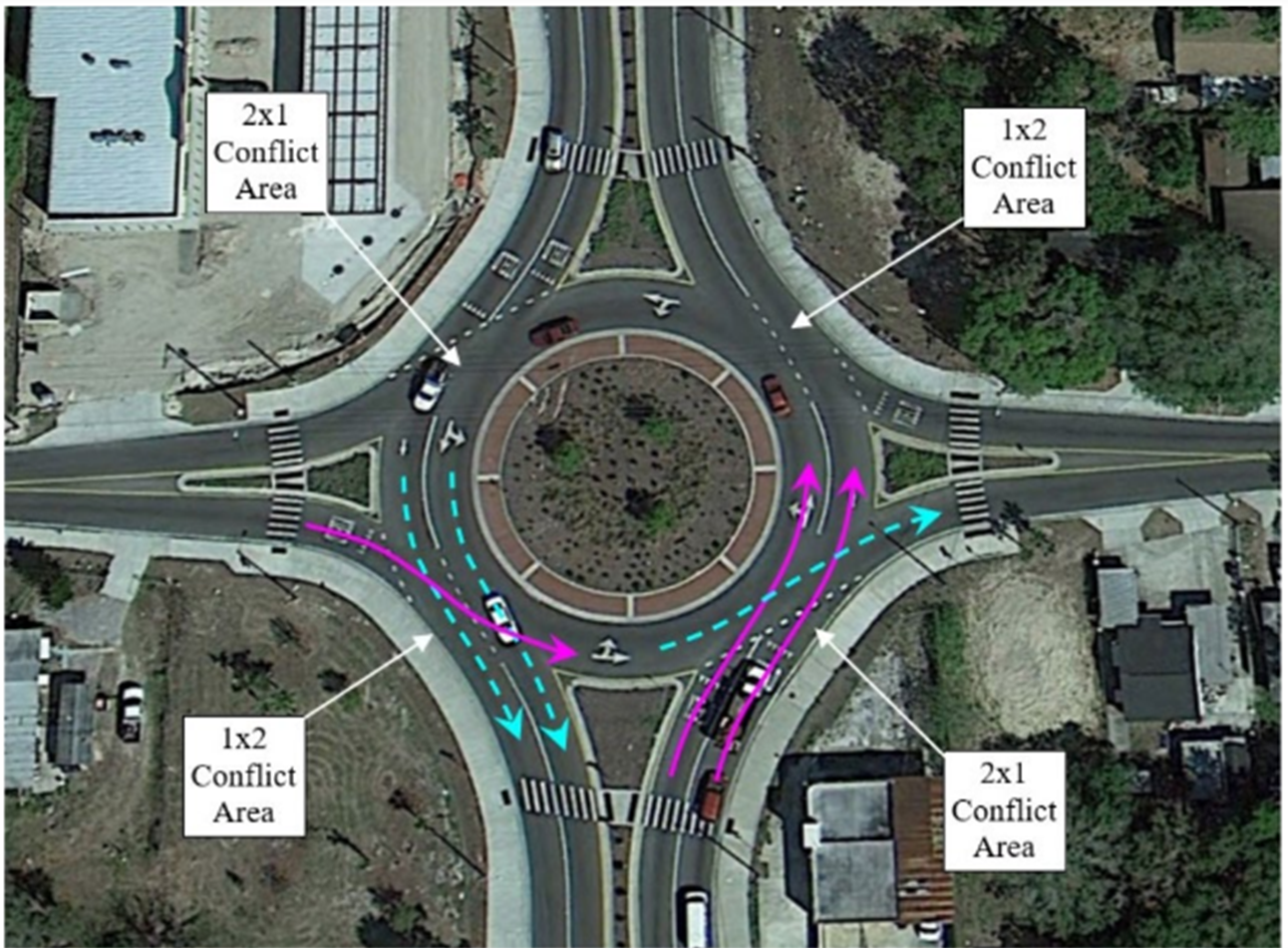
Figure 1: Example of a 2x1 roundabout configuration (Tampa, FL). (FHWA-HRT-23-023)
1. Define Conflict Areas
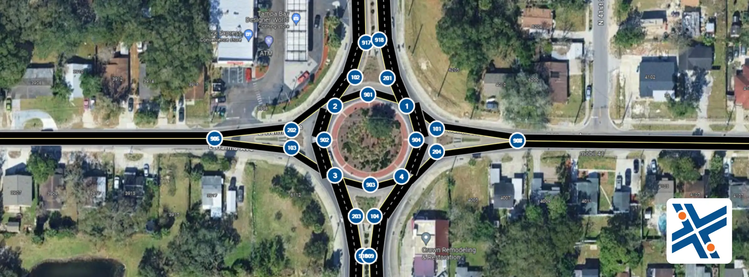
Set a node at each conflict area (Nodes 1-4 in the example file (Figure 2)).
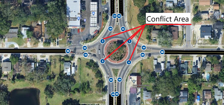
Figure 2: Setting Up Nodes for Conflict Areas (1-4) and Entry (101-104) and Exit (201-204) Links from Roundabout
2. Add Entry and Exit Nodes to the Roundabout.
Add nodes for entry-linked areas (Nodes 101-104 in this example) and exit nodes from the roundabout (Nodes 201-204 in this example).
3. Define Conflict Areas
Connect nodes with links, specifying the number of lanes as per your design. Add extra nodes for graphical purposes if needed (Nodes 901-904 in this example).
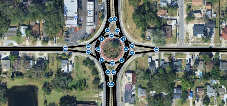
Figure 3: Creating links.
4. Add Yield and Stop Signs
Add yield and stop signs to the nodes at the conflict areas (Figure 4). Ensure the location of the stop line is adjusted accordingly (Figure 5).
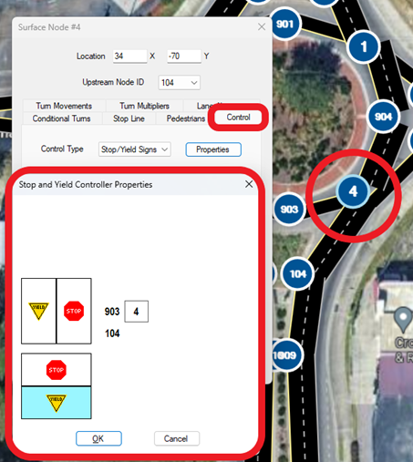
Figure 5: Adjusting the Location of Stop Line
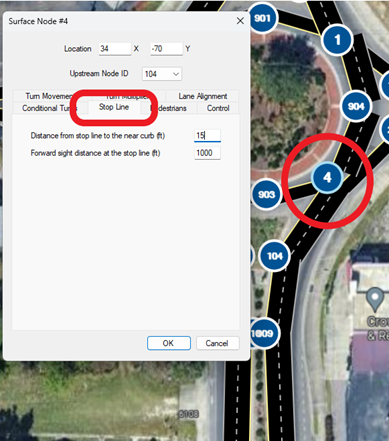
Figure 5: Adjusting the Location of Stop Line
5. Modify Lane Channelization
Adjust your lane channelization to match the field conditions (Figure 6).
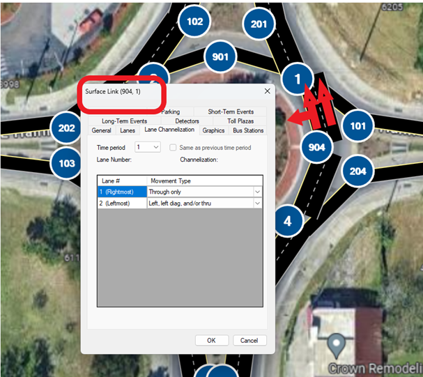
Figure 6: Adjust link alignment
The simulation is now ready to run.
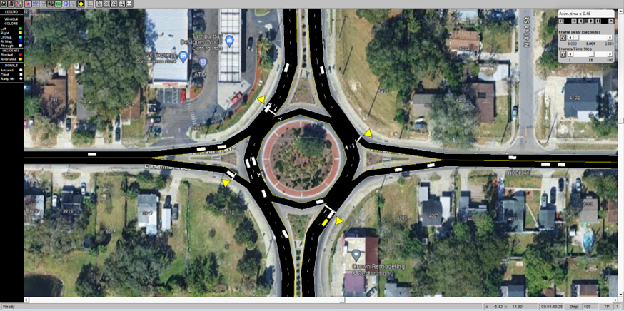
Figure 7: Run the simulation