
Dr. Ehsan Amini
Coordinating two closely spaced signalized intersections under a single traffic signal cabinet is common practice in the field. Ramp terminal intersections, for example, are a common use. This article will walk you through the steps required to model a pair of intersections operating on the same controller using TSIS-CORSIM.
1. Create and configure the network
- Lay out both intersections in TSIS Map View just as you would for independent nodes.
- In Node → Edit → Control, set every approach that will ultimately belong to the master controller (Intersection 1 in our example) to Actuated.
- Do the same for all approaches of Intersection 2 for now, this lets CORSIM build the needed detector and phase records automatically (easier to edit later).
- Save the file (e.g., paired_int_base.trf).
2. Run a test simulation:
- Run the simulation and make sure the project runs error-free. If any geometry or signal timing issues appear, fix them before touching the text editor.
Tip: Maintain this “clean” version of the file as a backup; it will allow you to revert to a stable state if any issues arise. Save As a new name (e.g., paired_int_one_ctrl.trf). All changes below are made in this copy.
3. Key CORSIM record edits
At this point, depending on your configuration, we need to modify these RTs.
Open the Text Editor: Tools → Editors → Text Editor and work through the Record Types (RTs) below.
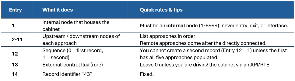
3.1 Record Type 43, Approach list for the actuated controller
RT 43 tells CORSIM which links the cabinet can “see”. Each record lists up to 5 approaches (10 if you add a second RT 43 for the same node). Only the first five may be direct approaches to the cabinet’s node; extra entries are “remote” approaches whose detectors influence the controller (perfect for a slave intersection)
Rule: “You cannot create a second RT 43 for a node until the first record lists five approaches.”
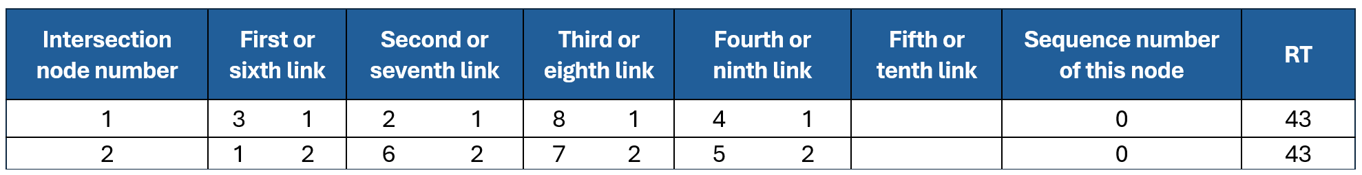
Since we want Intersection 2 to operate under the controller at Intersection 1, we must add the four approaches that physically terminate at Node 1 to the controller configuration at Node 2.
Therefore, in our example, we should modify RT43 as follows:
Before modification:
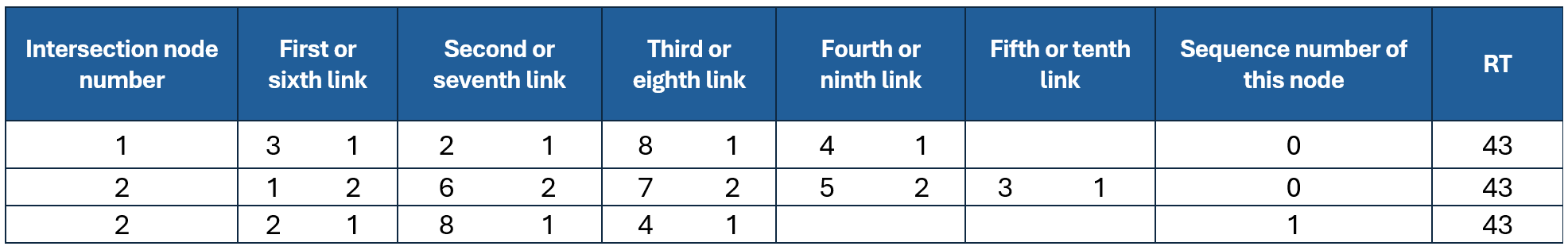
After modification:
3.2 Record Type 45, Allowed movements per phase
RT 45 specifies which movements (L / T / R / diag) are legal during each phase.
The entries for this RT are:
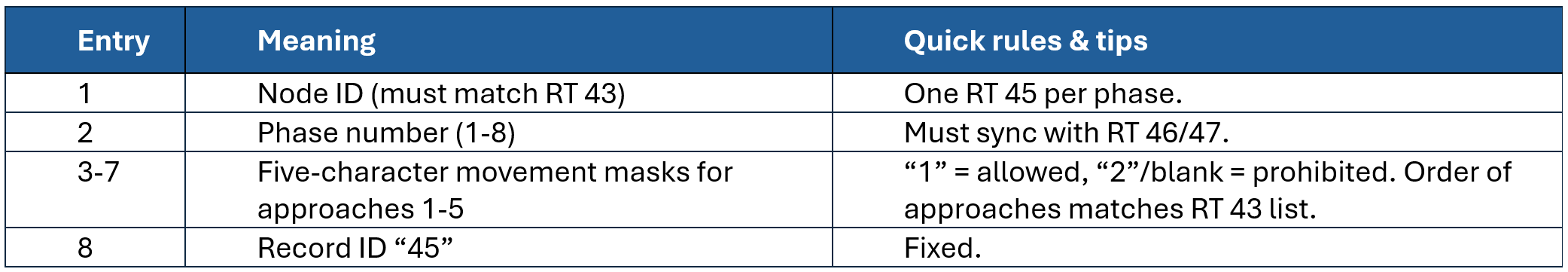
Because Intersections 1 and 2 share identical geometrics and you already built the phase logic in CORSIM, simply make sure the six RT 45 lines for Node 2 immediately follow the six for Node 1, no value changes required.
3.3 Record Type 46, Detector layout
RT 45 specifies which movements (L / T / R / diag) are legal during each phase.
The entries for this RT are:
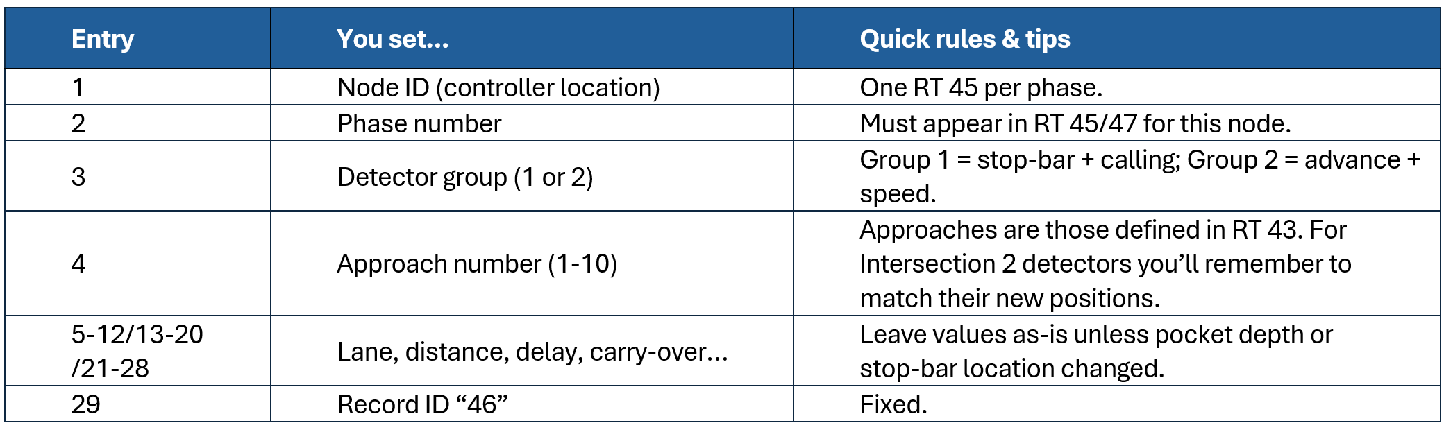
In our example for Intersection 2, we want to use loop detectors that are defined for approaches on Node 1. Therefore, we modify the approach numbers for Node 2 to reference the loop detectors assigned to the approaches for Intersection 1. By doing this, the signal at Intersection 2 will rely exclusively on the loops located on the approaches for Intersection 1.
Before modification:
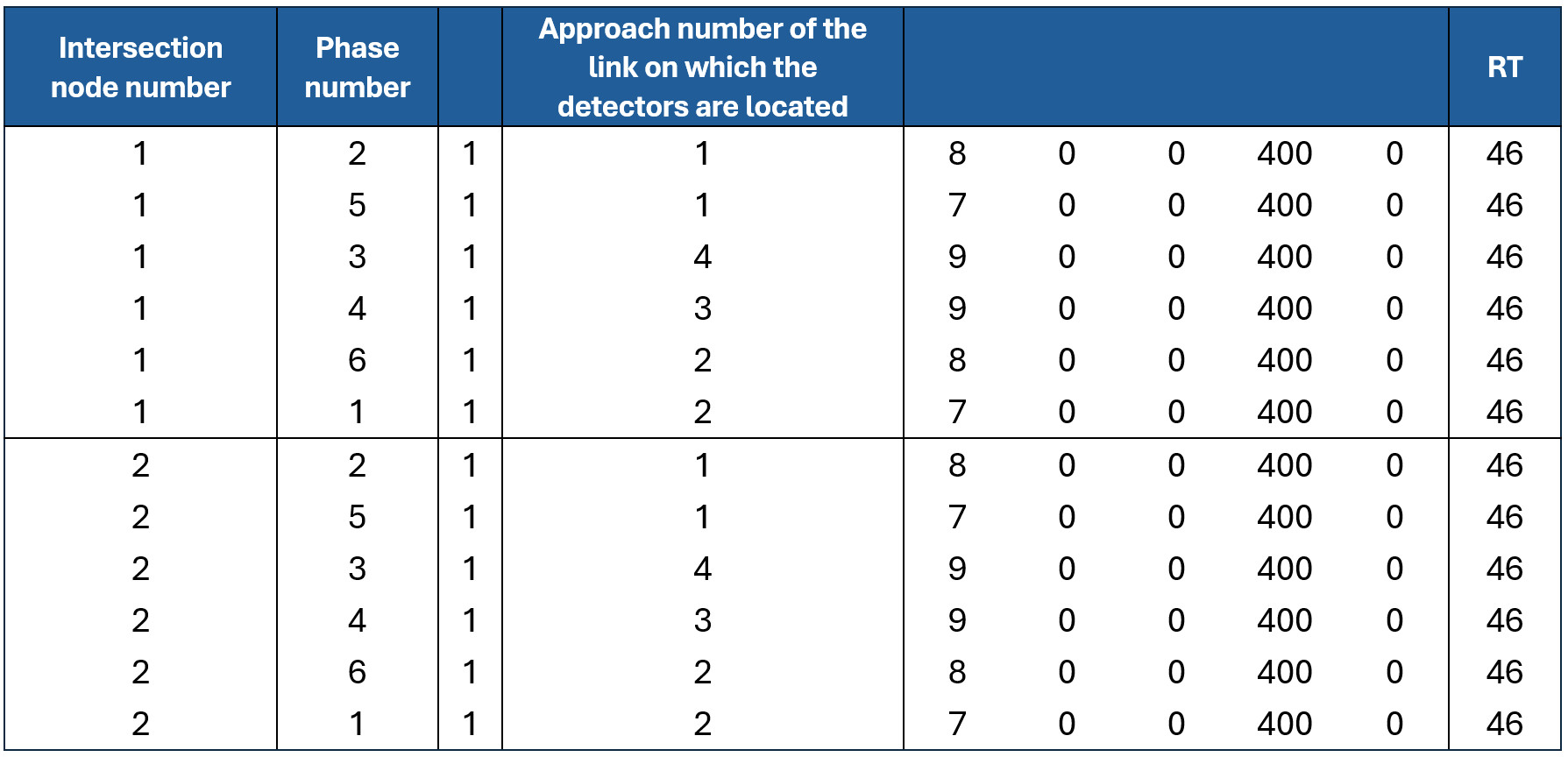
After modification:

You can modify this based on your needs. For example, if you want to use loops on Intersection 2 as well, you can add a new RT46 for Node 2 and define the loop detectors you want to include in that signal.
3.4 Record Type 47, Phase operations (timing parameters)
Record Type 47 defines the core parameters of actuated signal control, including green time, yellow time, passage time, gap reduction, recalls, and related operations. Each phase specified in Record Type 45 must have a corresponding entry in Record Type 47.
In this case, since we want Node 2 to operate under exactly the same signal control as Node 1, we can simply copy the signal plan from Node 1 to Node 2.
4. Validate Again
Run the simulation:
- If it crashes: verify that every RT 45 and RT 46 approach number exists in RT 43 and that each RT 47 phase exists in RT 45.
- Check detector counts on TRAFVU. If counts at Intersection 2 stay zero the phase numbers
or approach numbers in RT 46 don’t match. - Finally, verify that both intersections run under a single timing plan by watching greens change in sync in the animation.
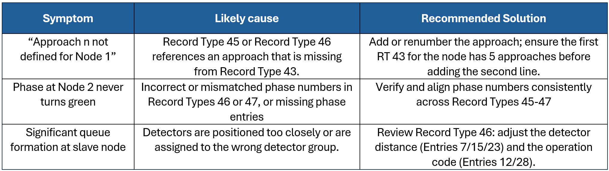
5. Common Pitfalls and Recommended Solutions
When configuring a pair of intersections under a shared controller in TSIS-CORSIM, several common mistakes may occur, potentially causing errors in the simulation. The table below summarizes the most frequent pitfalls, their likely causes, and practical solutions to help users troubleshoot and resolve these issues.
5. Takeaways
Integrating multiple intersections under a single controller in TSIS-CORSIM is entirely a text-based configuration process; the TSIS graphical user interface (GUI) does not provide automated support for this task.
Maintain a clean backup of the configuration files and consider using a file comparison tool to track and verify changes, particularly if troubleshooting becomes necessary.
It is essential to edit Record Type 43 first, as all subsequent records rely on the approach order defined within it.