
Dr. Fabio Sasahara
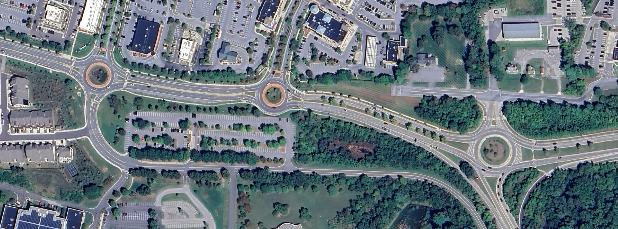
Roundabouts are increasingly used not only as isolated intersections but also as components of urban corridors. Traditional roundabout analysis focuses on the operational performance of an individual roundabout, evaluating approach capacity, control delay, queues, and level of service (LOS). However, when multiple roundabouts are connected by urban street segments, the operational performance of the corridor depends on more than just the operation of each intersection. Travel speed, running time, geometric influence, and interactions between adjacent roundabouts become important considerations.
To address these situations, the Highway Capacity Manual (HCM) 6th Edition introduced the Roundabout Segment Methodology in Chapter 30, Section 9, for evaluating urban street segments bounded by one or more roundabouts. This methodology supplements the isolated roundabout analysis procedures contained in Chapter 22.
Analyzing an Isolated Roundabout
The most common use of the HCM Methodology for roundabouts (Chapter 22) is to evaluate the operational performance of a single, isolated roundabout. The primary focus is on determining:
- Entry capacity
- Volume-to-capacity (v/c) ratio
- Control delay
- LOS, based on control delay
- 95th percentile queue length
The capacity models used in this method are fairly simple, where capacity of an entry lane decreases with higher circulating flows. Different capacity equations are used depending on the number of entering and circulating lanes. The methodology, however, is not sensitive to geometric factors such as Inscribed Circle Diameter (ICD), lane width, circulatory roadway width, entry/exit radii, and splitter island dimensions.
Urban Street Segment Analysis
HCM Chapter 18 (Urban Street Segments) is commonly used to evaluate street segments bounded by intersections. This method produces the following outputs:
- Running time
- Travel speed
- Stop rate
- Spatial stop rate
- LOS, based on travel speed (segment and facility-wide)
For the special case when the segment is bounded by one or more roundabouts, a variation of the procedure is applied, as described in HCM Chapter 30 (Urban Streets Supplemental). This chapter can be accessed through the HCM Volume 4 website.
Roundabout Segment Analysis
The Urban Street Segments methodology (HCM Chapter 18) is the basis for the roundabout corridor analysis, with some variations such as:
Free-flow Speed
A different procedure is used to compute FFS when roundabouts are presents. Given that entering and exiting speeds in a roundabout differ from traditional intersections, the presence of a roundabout also affects the speeds at the adjacent segment.
Through delay
In the Urban Streets methodology, the through delay at the downstream intersection is added to the travel time in the subject direction. For traditional intersections, the through delay is comparable to the control delay associated with the intersection. For the case of roundabouts, the through delay incorporates not only the control delay, but also an additional component called geometric delay.
The geometric delay can be interpreted as the additional time required to travel through a roundabout in a circular path, compared to a straight-line trajectory in a traditional intersection – the figure below illustrates the concept.
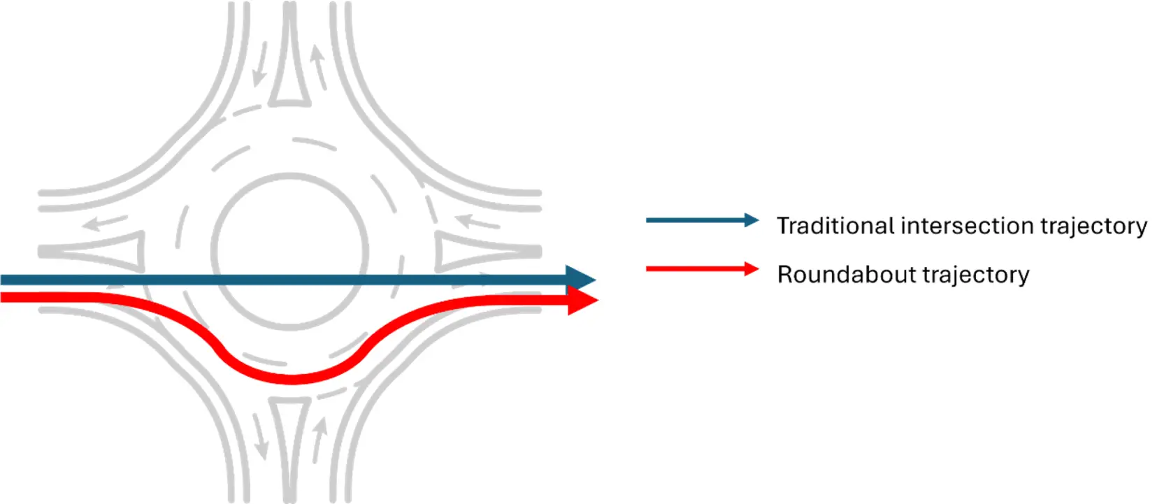
Comparison of trajectories for the thru movement – traditional intersection vs roundabout
Since the calculation of the geometric delay depends on roundabout geometry, two new inputs are required when evaluating roundabout corridors:
- Inscribed Circle Diameter (ICD)
- Average circulating lane width
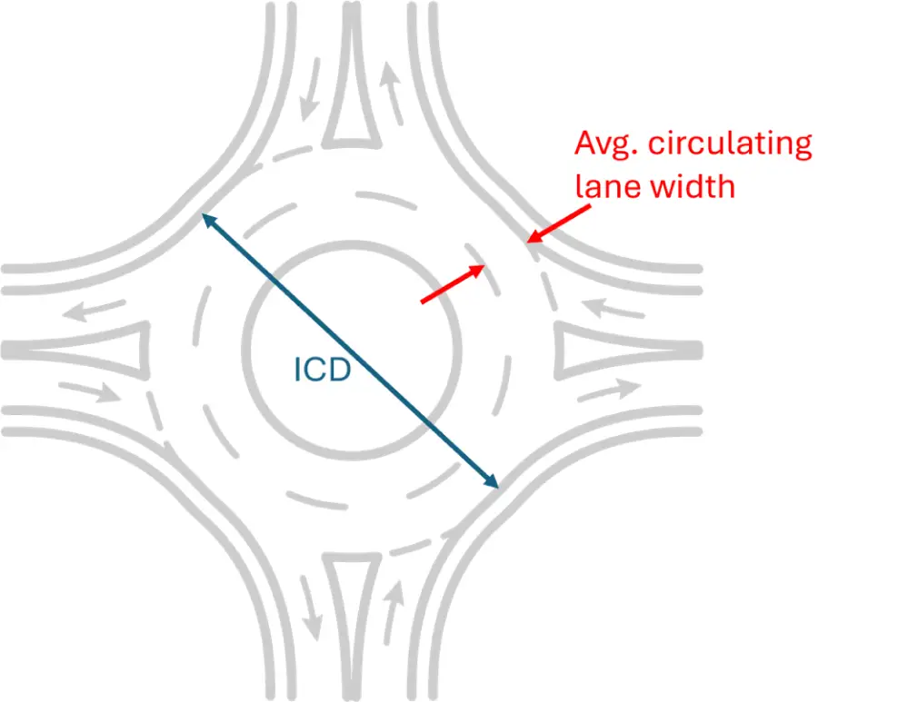
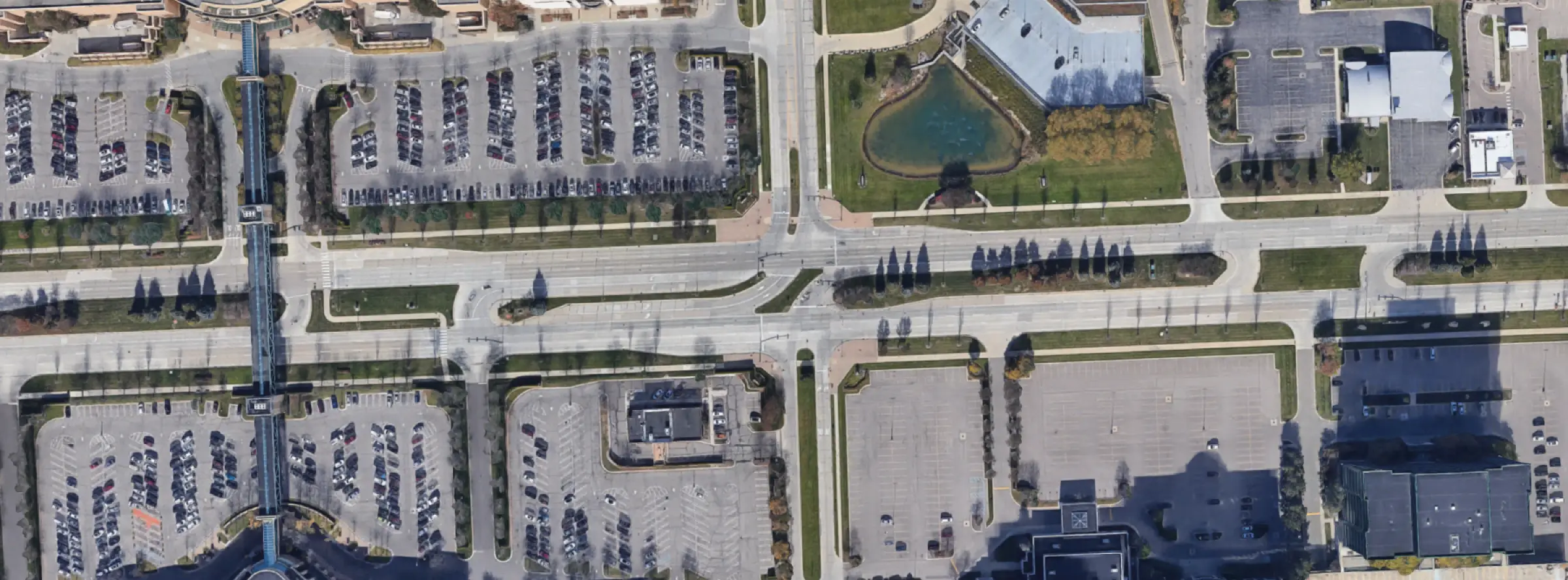
Measuring ICD and average circulating lane width
Modeling a Roundabout Corridor in HCS
A roundabout corridor can be modeled in HCS through the following steps:
Step 1
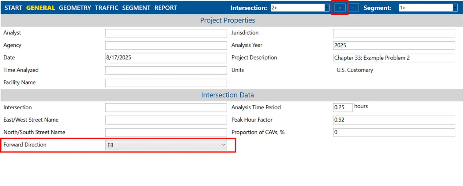
Create the first roundabout using the Roundabouts module. Then, click the “+” button on the top right portion of the screen to add one or more additional roundabouts. For every additional roundabout added, a new segment will be added as well. When at least two roundabouts are included in the model, the “Forward Direction” input can also be defined in HCS.
Step 2
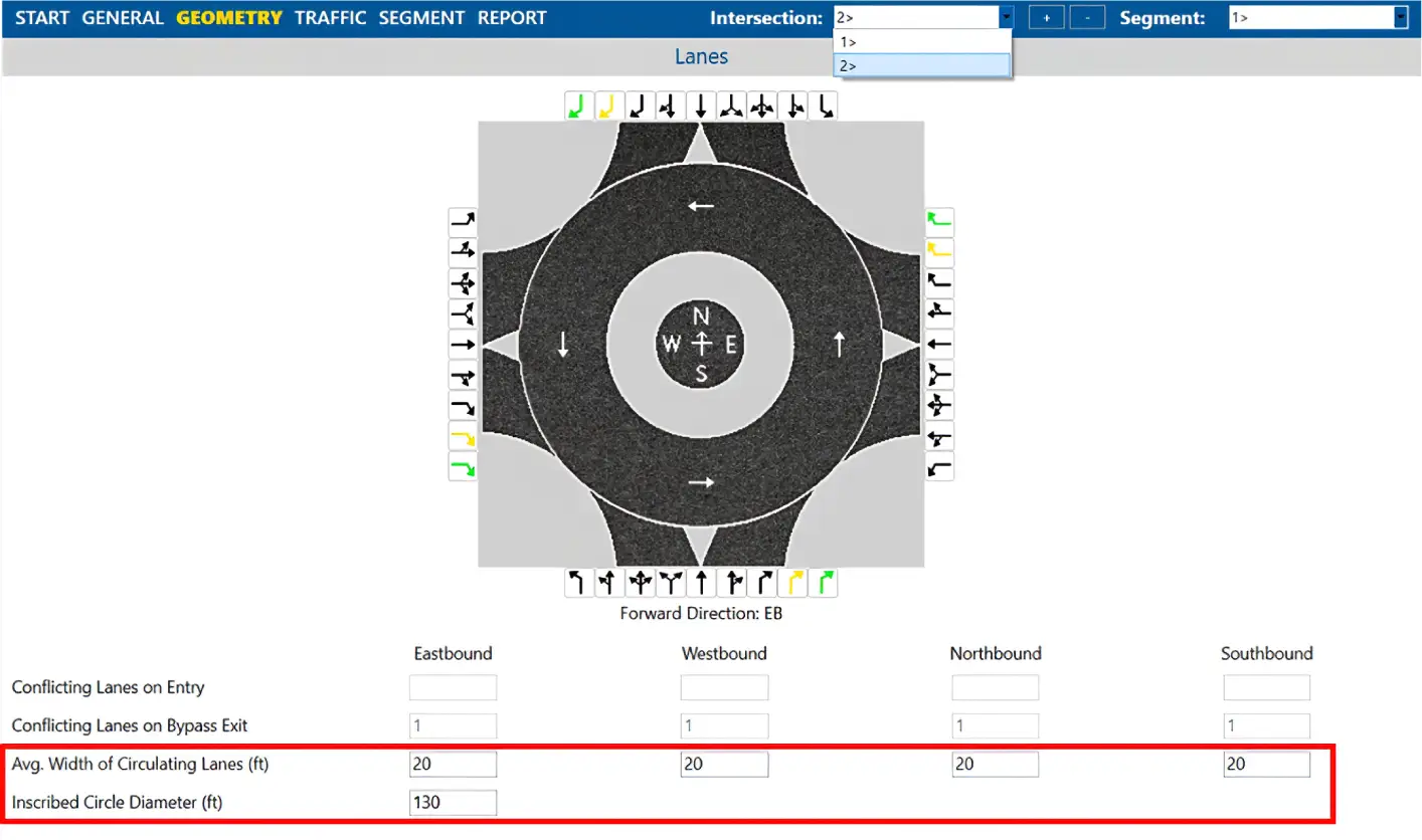
Provide the required inputs for all roundabouts in the corridor, similar to the first one. When at least two roundabouts are included in the model, two additional geometric inputs will be available in the “Geometry” page.
Step 3
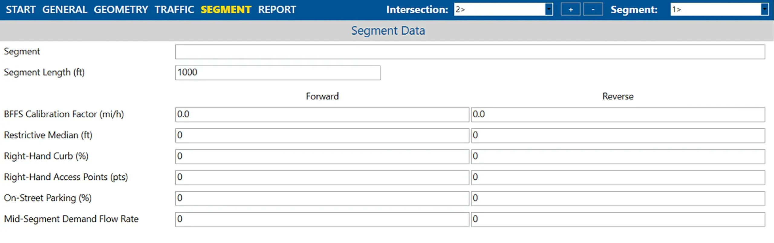
Navigate to the “Segment” page (only available for roundabout corridors) and enter the required inputs for each segment. For details on the inputs, please refer to HCM Chapter 18 – Urban Street Segments.
Step 4
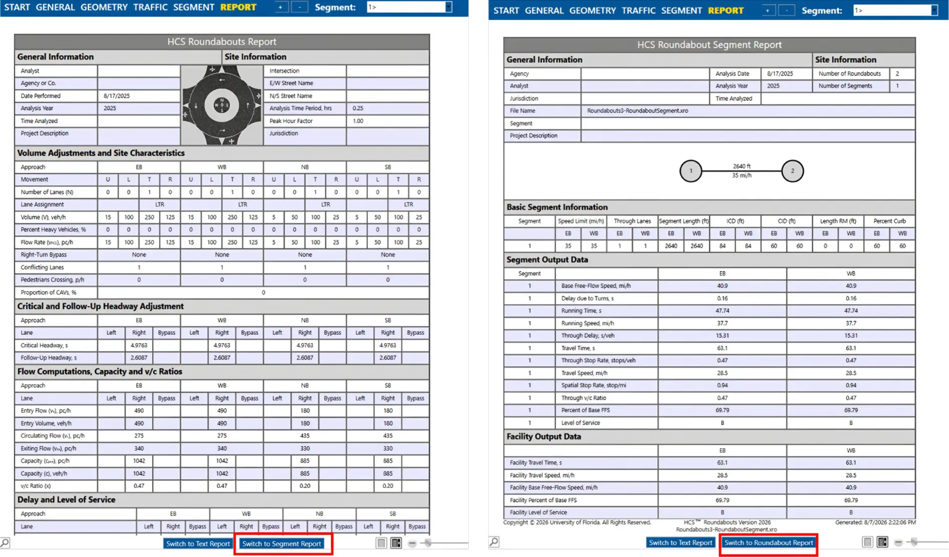
The segment report can be accessed in the “Report” page. You can toggle between the individual roundabout and the segment reports by clicking the buttons on the bottom of the page.